- #GE FANUC VERSAMAX PROGRAMMING CABLE RJ12 PINOUT HOW TO#
- #GE FANUC VERSAMAX PROGRAMMING CABLE RJ12 PINOUT UPDATE#
- #GE FANUC VERSAMAX PROGRAMMING CABLE RJ12 PINOUT DRIVER#
- #GE FANUC VERSAMAX PROGRAMMING CABLE RJ12 PINOUT MANUAL#
#GE FANUC VERSAMAX PROGRAMMING CABLE RJ12 PINOUT MANUAL#
This manual describes the system operation.
#GE FANUC VERSAMAX PROGRAMMING CABLE RJ12 PINOUT DRIVER#

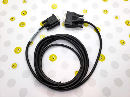
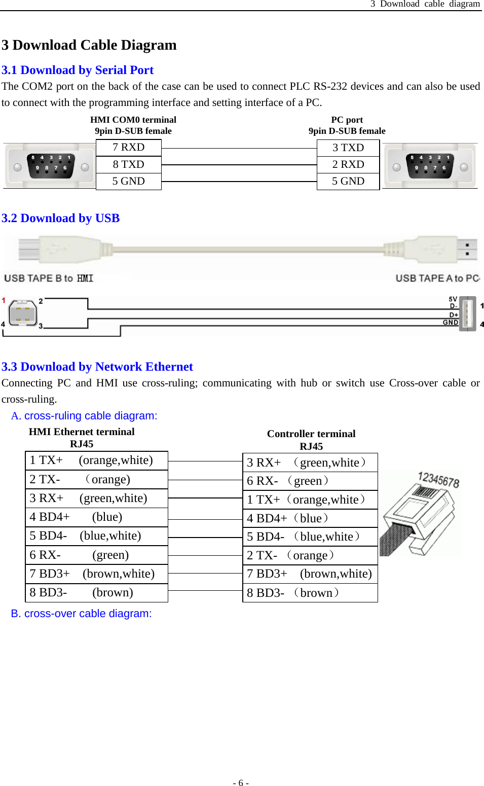
and 15: 2 RX 6 RX 8 RX 3 TD 5 GND 5 GND 5 G.and 13: Driver Version: Version Date Descri.If you should have a problem installing or programming your GE Fanuc Micro PLC, and the information you need is not in this book or the Micro PLC Programmers Guide, you can call GE Fanuc Field Service at 1-80. and 11: Device address: AI-518 Bit/Word Dev At GE Fanuc, we strive to produce quality documentation.Use the RS422 to RS232 PLC programming cable (show as. and 9: Port Splitter cables for MT-6000 an Memo90 VersaMax series PLC of GE FANUC includes such series as 90.

and 7: Chapter 6: PLC Connection Guide Ext.and 5: 4 PLC Connection Guide TECO Inverte.Metric Unit versions are available upon request. In this version, like all the PLC versions, the gains have been applied and the units have been converted to US unit. PLC with the Gateway acting as the Master device. and 3: 2 PLC Connection Guide KERNEL SISTE FORM-C, SPDT contacts for signaling a High/Low Alarm and Radio Communication. The GE Fanuc version gathers all Engine Data and creates a data map that is pushed to the.After wiring is finished, remove the paper used as a dust cover before starting to operate the. Set LW-9903 to 2 to enhance the speed of download/upload PLC program in. GE Fanuc, Hitachi, Hitachi Industrial Equipment Systems. 23 Allen Bradley EtherNet/IP-Tag (CompactLogix/ControlLogix). Wiring Diagram: The following is the view from the soldering point of a cable.

17 Allen-Bradley EtherNet/IP CompactLogix. 5 Allen-Bradley CompactLogix / FlexLogix.
#GE FANUC VERSAMAX PROGRAMMING CABLE RJ12 PINOUT UPDATE#
The information in these cable tables is subject to change without notice as we continue to update and expand our custom cable offering.PLC Connection Guide 1 PLC Connection Guide AIBUS. Note: A maximum cable length of 10 feet between the Micro-Graphic panel and the PLC is recommended when powering the panel from the PLC. If you are unsure which cable you need or wish to place an order, contact Sales for assistance at: or call (425) 745 3229. Set LW-9903 to 2 to enhance the speed of download/upload PLC program in. connections of available cables plus wiring diagrams that the user can refer to in order to construct their own cables, along with wiring diagrams of cables that are not available for purchase. Big and bad seven amp relays We used the most powerful relays in a micro and combined them with a design that sheds heat The DL105 offers eight relay outputs that can support up to 7 A. Please double-check to make sure you have identified the proper cable for your unit as all custom cables are made to order and are non-refundable. ible 1.6 A per point Compare this to the GE Fanuc Series 90 micro, which offers only 0.5 A and 14 I/O points at a whopping.
#GE FANUC VERSAMAX PROGRAMMING CABLE RJ12 PINOUT HOW TO#
The word, "instructions" means that we do not make the cable but we do provide instructions to show you how to make one yourself. Note: If you see a blank space, it means we may not currently provide a cable or instructions for that controller.


 0 kommentar(er)
